Thursday, June 9, 2011

Stereo Gain Audio Trim Control Circuit

Audio Gain Control With Digital Potentiometers

Stereo Gain Audio Trim Control Circuit

This circuit using the MAX5160L digital pot in a divider chain supplying the MAX4252 op amp with some positive feedback in addition to the usual negative feedback via the 100K and 50K resistors. The gain of this circuit can be shown to be:

AV = (1-Kn)/(Kp-Kn)

where Kn is the negative feedback fraction, Kp the positive feedback fractions (for the example in Figure 4, Kn = 100K/(100K + 50K) or 2/3, and Kp is variable).

When the MAX5160L wiper is positioned at the VREF terminal, the gain of the circuit is -0.5V/V, as there is no positive feedback contribution. When the wiper is at mid scale, Kp = 0.5, and the gain is now -2V/V. Hence, by using those 17 positions between VREF and midscale the gain can be varied over a ±6dB range. The 15 unused positions have been traded off for repeatability, as the gain value does not depend upon the digital pot resistance tolerance, as did the circuit of Figure 1. The gain tolerance is now only limited by the ±1% 100K/50K resistors, and the INL/DNL error of the MAX5160L (±4.6% max.).

An interesting point to note, the limit for stability in this circuit is reached when Kp ≥ 2/3, when the positive feedback fraction meets or exceeds the negative. The host processor controlling the MAX5160L should therefore prevent this situation occurring.

The circuit in Figure 5 shows an obvious appraoch to a 'traditional' style volume control using digital pots. All codes are valid, with settings ranging from 0dB to full attenuation. Table 1 shows the calculated attenuations based on the MAX5160L's 32 steps.

Nestbox Solar Powered Wireless CCTV Camera Circuit

Below is the circuit used to power the CCTV camera, provide lighting inside the nestbox, and charge batteries from a PV solar panel.
Circuit diagram for CCTV powered by Solar Panel with Battery Backup


D1 is a Schottky Diode used to prevent battery charge escaping through the solar panel at night. Something like a 1N5817 (1 Amp 20 Volt diode) will do the job and it has a very low voltage drop of under 0.45 Volts. D2 and D3 are ultrabright LEDs used to illuminate the inside of the nestbox. R3 and R4 are resistors chosen (400+ Ohms) to ensure that no more than 30mA of current gets to the sensitive LEDs, with R5 (a 10k variable resistor) used to increase the resistance and therefore dim the LED s if they are too bright.The LM317T is a voltage regulator * used to bring the voltage of the solar panel and batteries down to just over 8 volts using resistors R1 (270 Ohm) and R2 (1500 Ohm) to set this value. K is the wireless CCTV camera. A switch (not labelled) is used to manually turn the camera on and off as required.

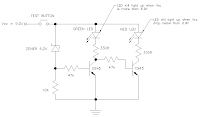
Extra - Low battery indicator

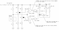
The extra circuit supplied is to check the battery condition.
Low battery voltage (below than ~6.9V) will show "RED" light up.
Else will show "GREEN" LED light up.
The basic, if there is a small amount of current go through the zener (reverse bias),
the first transistor (left) will be turned on making the "GREEN" LED turn on.
Other than that the second transistor (right) will be turned on and "RED" LED will light up.


Modification - Add in buzzer


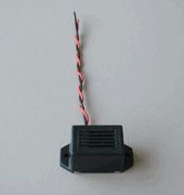
You add in buzzer to the circuit to make it give an audible alarm.
The best is to alert us whenever the cable under test is not "GOOD".
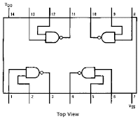
So, adding a resistor, transistor and a buzzer/beeper to the last NAND (near "GOOD" LED) will do the job.
Use your own creativity for this. :-).

Simple Cable Tester

Simple DIY Cable Continuity Tester


How to use


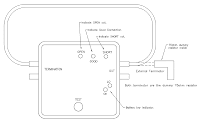
This simple cable tester can be used to check 2 wire cable such as coax cable, telephone cable, audio cable and etc.
Power the circuit using 9V battery.
Plug in the cable and push "TEST" button.
The dummy resistor is connected to the end of the cable which has 75ohm resistor inside.
The tester will show only 3 conditions, "SHORT", "OPEN" and "GOOD".


How it works


The method is to check resistance of the dummy resistor at the "Terminator".
The idea is simple.
Imagine there is a short circuit cable under testing.
The wire will act as nearly zero ohm resistor thus making the voltage divider near the dummy resistor to divide the 9V into 4.5V.
Calculate it your self [ ( 1k / ( 1k + 1k ) ) * 9V = 4.5V ].
4.5V is below than the lower "Comparator" limit (Vref 4.57V).
It will trigger the lower "Comparator" and make "Short" LED to light up.
Now for the open circuit cable.
Assuming the open circuit cable has an infinite ohm.
Voltage divider near the dummy resistor will give 9V.
This is more than the upper "Comparator" limit (VRef 4.8V) and will trigger make "Open" LED light up.
Other than that (both lower and upper "Comparator" didn't trigger) the "GOOD" LED will light up.
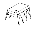
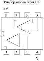
For the op-amp, I'm using JRC4558 dual op-amp since I have it in my stock.
You may use 741 op-amp or other multi-purpose op-amp.
Learn more about op-amp here


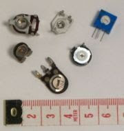
Vref tuning


Before turning on the circuit (power it up),
tune the potentiometer so that it will give the correct voltage reference to the "Comparator"s.

  • Upper "Comparator" = 4.8V
  • Lower "Comparator" = 4.57V