Saturday, December 23, 2006

Biquad ant. for WLAN

Biquad Antenna for 2.4 GHz - 802.11b/g - WiFi - WLAN


After some research, I found out that the simplest type of
homemade WLAN antenna is BiQuad antenna. Many sites provide good
instruction on how to assemble it.

(refer below)


I'm not going to repeat it.

My Antenna


So I start by recycling some parts that I found in my workshop
and construct it.


I took about 10-20 min. for me to finished it.


The critical process is to make the element.

With proper method and dimension this thing will work.


Good Luck!!!

Thursday, August 3, 2006

ATX PSU Diagnose

About ATX Power Supply


ATX Power Supply converts the wall (AC) to the direct current (DC) needed by the
PC. The power supply looks like a metal box with fan.
Typical computer power supply generates the voltages needed by the computer motherboard accessories.
[Read more...]


Before Everything


Disconnect all socket from your main board, HDD, CD/DVD drive, Floppy drive and etc so that we can isolate which part
is not working.


Step 1 - Check Wall AC power


To check this, you may try to plug in any electrical appliances to the wall socket to verify that the 240V exist
such as lamp, table fan or etc. If it is working, that mean the power from the wall socket is ok.
You may also check the voltage with multimeter if you have one.


Step 2 - Power Socket Fuse


If you are using power socket with fuse, you may try to check this first.
The method is to plug the other end to other appliances such as your printer (turn on to verify),
monitor (turn on and look for LED indicator) or rice cooker (My rice cooker using the same type of socket).
Same thing, if it is ok, we know up to the power cord is also ok.


Step 3 - Voltage Selector


Not all power supply have this switch. My place using 240VAC.
So if it accidentally set to 110VAC the power supply maybe burn out. No more further troubleshooting.
But at place with 110VAC, maybe it will not burn out when it accidentally set to 240VAC.
It will in the low voltage condition and may not start I presume.
Select the correct voltage according to power provider rating.


Step 4 - 5V+ Standby Voltage


From bluemax.net


The first point that have voltage upon plug in the AC power is the standby voltage.[refer figure above]
5VSB constantly provides 5V power to the connector at pin 9.
Check this voltage using volt meter to make sure that 5V exist (while the AC is turn on).


Step 5 - Simulate Power On


Now is the interesting part. To turn on your ATX power supply without mother board, the way is to make contact
between pin 14 and ground pin(3,5,7,13,15,16,17). Meaning you can turn it on by connecting pin 14 with the only green wire
connecting to it to other ground pin that is the pin with black wire. To verify that the power supply is working,
the ventilation fan should be working split second after you connect pin 14 to ground. Paper clip would be the best choice.


Step 6 - Check All Output


Now you can check all voltage output from the power supply. You need a voltmeter in order to do that.


Pin Name   Color Description
1 3.3V   Orange +3.3 VDC
2 3.3V   Orange +3.3 VDC
3 COM   Black Ground
4 5V   Red +5 VDC
5 COM   Black Ground
6 5V   Red +5 VDC
7 COM   Black Ground
8 PWR_OK   Gray Power Ok (+5V & +3.3V is ok)
9 5VSB   Purple +5 VDC Standby Voltage (max 10mA)
10 12V   Yellow +12 VDC
11 3.3V   Orange +3.3 VDC
12 -12V   Blue -12 VDC
13 COM   Black Ground
14 /PS_ON   Green Power Supply On (active low)
15 COM   Black Ground
16 COM   Black Ground
17 COM   Black Ground
18 -5V   White -5 VDC
19 5V   Red +5 VDC
20 5V   Red +5 VDC


From bluemax.net


Good Luck

Wednesday, May 10, 2006

S/PDIF - TOSLINK interface

Circuit & Information on TOSLINK interface


So you want to get a high quality audio for minidisc recording but when
using red and white RCA, the quality drop drastically. Here a my cheap solution for you.
Actually you can find a lot of references of this type of simple project in the internet.


REF


* S/PDIF = Sony/Philips Digital Interface

* TOSLINK = (

TOSLINK Interconnect History & Basics

)

* Another web offering the same information


* SPDIF at epanorama.net


Meet my version of cheap, 2 components TOSLINK @ S/PDIF.
Try to find a cable with connector from old PC casing for this.
(HDD led,reset switch or power button connector)


Assemble it using your own creativity. Use the pen tube for the light transmission.


Connect it to the back of your CDROM drive. Since (D, the signal should go to anode and G should go to the ground/cathode)


Test it out. you should see the light come out from the tip/tube.


Connect to your MD or other device such as power amp that support optical in.


Actually, I have one of this (USB to SPDIF converter) for my minidisc but just to share with you on how to find a supercheap
solution before start buying. :-)


Even my new MSI mainboard do have built-in TOSLINK :-)

Friday, May 5, 2006

PC IrDA interface

DIY IR interface


This circuit is also from www.electronics-lab.com.
Since it is very hard for me to get the infrared interface (TFDU4100), I start to look in the old/damage handphones.
It looks something like this.


Now, you need to remove it using the hot air blower perhaps.


Connecting to motherboard


Please refer to www.electronics-lab.com
on how connect this irda module to your motherboard.

My IrDA


Infrared Transceiver Modules


Here are the pin layout and picture of the device.


Pin Description of TFDU4100


Pin Number Function Description I/O Active
1 IRED Anode
IRED anode, should be externally connected
to VCC2 through a current control
resistor
2 IRED Cathode
IRED cathode, internally connected to
driver transistor
3 Txd Transmit Data Input 1 High
4 Rxd
Received Data Output, open collector.
No external pull–up or pull–down resistor
is required (20 k. resistor internal to device).
Pin is inactive during transmission.
0 Low
5 NC Do not connect
6 VCC1/SD Supply Voltage / Shutdown
7 SC Sensitivity control 1 High
8 GND Ground

Wednesday, April 26, 2006

Touch Switch


Experiment With NAND Gate - CMOS 4011


Output goes high when touch wires bridge by finger.

Gates Oscillator

Experiment With NAND Gate - CMOS 4011


(CMOS 4011 Layout)


Circuit


Try this super-simple experiment. The output frequency is about 1kHz (square wave).

Wednesday, April 19, 2006

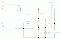
Telephone FM Transmitter

Descrition & Circuit


This project is taken from www.electronics-lab.com.

With some modification, I create my own version of FM Telephone bug complete with stripboard layout.

Theortically, the frequency range is from 88MHz to 94MHz but you may experiment with the coil structure to tune it


Circuit


Strip Board Layout


Parts List


Diode IN4384 4
LED 1
Resistor 12k 1
1k 1
200R 1
Capacitor 470p 1
330p 1
25p 1
12p 1
Transistor A933(PNP) 1
Coil *See note 1

*Coil note

7 or 8 turns of 22AWG(diameter .6mm) around 9/64inch(3.6mm)
drill bit. Antenna using the same wire 22AWG, 5inch long

Picture


Compact!


With antenna!


Put it online!


Get ready to tune your radio!

Monday, April 10, 2006

Lab Power Supply

Description and Circuit


Make your own lab power supply complete with adjustable voltage and constant current source.

Using single IC (LM324)


Here is the circuit.


Strip Board Layout.


Part List


1 LM324 Opamp

1 Ammeter 100 µA 1k ohm

1 Voltmeter

6 IN4001

1 Zener Diode 9.1V

1 Full-Wave Bridge Rectifier

1 LED

2 NPN Transistor, 2N3055

1 NPN Transistor, BC109C

1 Transformer

2 E-Capacitor 2200µF

1 Potentiometer 5k ohm linear

1 Potentiometer 10k ohm linear

1 Resistor 500 ohm

2 Resistor 2.2k ohm

1 Resistor 560 ohm

1 Resistor 6.2k ohm

2 Resistor 68k ohm

1 Resistor 0.22 ohm

4 Resistor 4.7k ohm


Component Image.


LM324


2N3055


Some Pictures.