Blog Archive
-
▼
2010
(297)
-
▼
August
(35)
- LED FLASHER ( About 1Year )
- 1.2GHz Voltage Controlled Oscillator With Linear M...
- Standard Tube Lamp Disco Light Strobo Circuit
- TDA2004 Stereo Car Radio Amplifier Circuit
- Anti Theft Car wireless alarm
- Game Show Timers Schema electronic Circuit
- Electronic Circuit Symbols Components
- Dome light dimmer With delay for Cars
- Wiper Speed Control Circuits
- Charge Monitor For 12V Lead Acid Battery
- RF Transceiver Module - High Frequency RF Transcei...
- WIRELESS USB DONGLE - AWP24U
- Wireless USB - RF Transceivers™
- transmitters modules at 433.92MHz
- 2.4 Ghz. Transceiver - RF Transceiver-OEM
- New 2.4 GHz RF Transceiver Nodules
- A Simple Electronic Buzzer electronic
- 9V (2A) power supply circuit diagram
- Schema HO Train Model Lighthouse Flasher
- Trigger Input Control Of 555 Timers
- Ding Dong Bell circuit diagram
-
▼
August
(35)
CONTACT US
to report broken link please email to:
scemaelectronic@gmail.com
Total Pageviews
Link List
ANALOG COMPONEN
Blog Archive
-
▼
2010
(297)
-
▼
August
(35)
- LED FLASHER ( About 1Year )
- 1.2GHz Voltage Controlled Oscillator With Linear M...
- Standard Tube Lamp Disco Light Strobo Circuit
- TDA2004 Stereo Car Radio Amplifier Circuit
- Anti Theft Car wireless alarm
- Game Show Timers Schema electronic Circuit
- Electronic Circuit Symbols Components
- Dome light dimmer With delay for Cars
- Wiper Speed Control Circuits
- Charge Monitor For 12V Lead Acid Battery
- RF Transceiver Module - High Frequency RF Transcei...
- WIRELESS USB DONGLE - AWP24U
- Wireless USB - RF Transceivers™
- transmitters modules at 433.92MHz
- 2.4 Ghz. Transceiver - RF Transceiver-OEM
- New 2.4 GHz RF Transceiver Nodules
- A Simple Electronic Buzzer electronic
- 9V (2A) power supply circuit diagram
- Schema HO Train Model Lighthouse Flasher
- Trigger Input Control Of 555 Timers
- Ding Dong Bell circuit diagram
-
▼
August
(35)
Tuesday, August 31, 2010
LED FLASHER ( About 1Year )
This is so useful circuit diagram for you Because this circuit can light up an LED about 1 year with 9V battery.Here I have used famous IC HEF 4093.
Note
# Use a white colour LED
# Build this on a PCB to get maximum result
# Use 9V battery to power this circuit
Sunday, August 29, 2010
1.2GHz Voltage Controlled Oscillator With Linear Modulation
Standard Tube Lamp Disco Light Strobo Circuit
TDA2004 Stereo Car Radio Amplifier Circuit
Saturday, August 21, 2010
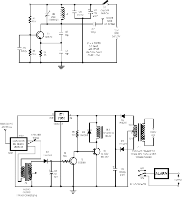
Anti Theft Car wireless alarm
Game Show Timers Schema electronic Circuit
Electronic Circuit Symbols Components
Drawing ambit diagrams
Drawing ambit diagrams is not difficult but it takes a little convenance to draw neat, bright diagrams. This is a advantageous accomplishment for science as able-bodied as for electronics. You will absolutely charge to draw ambit diagrams if you architecture your own circuits.
Follow these tips for best results:
Make abiding you use the actual attribute for anniversary component.
Draw abutting affairs as beeline curve (use a ruler).
Put a 'blob' () at anniversary alliance amid wires.
Label apparatus such as resistors and capacitors with their values.
The absolute (+) accumulation should be at the top and the abrogating (-) accumulation at the bottom. The abrogating accumulation is usually labelled 0V, aught volts.
If you are cartoon the ambit diagram for science amuse see the area about cartoon diagrams the 'electronics way'.
If the ambit is complex:
Try to align the diagram so that signals breeze from larboard to right: inputs and controls should be on the left, outputs on the right.
You may omit the array or ability accumulation symbols, but you charge accommodate (and label) the accumulation curve at the top and bottom.
Drawing ambit diagrams the 'electronics way'
Circuit diagrams for electronics are fatigued with the absolute (+) accumulation at the top and the abrogating (-) accumulation at the bottom. This can be accessible in compassionate the operation of the ambit because the voltage decreases as you move bottomward the ambit diagram.
Circuit diagrams for science are commonly fatigued with the array or ability accumulation at the top. This is not wrong, but there is usually no advantage in cartoon them this way and I anticipate it is beneath accessible for compassionate the circuit.
I advance that you consistently draw your ambit diagrams the 'electronics way', alike for science!
[I achievement your science abecedary won't apperception too much!]
Note that the abrogating accumulation is usually alleged 0V (zero volts).
This is explained on the Voltage and Current page.
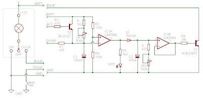
Dome light dimmer With delay for Cars
Wiper Speed Control Circuits
Charge Monitor For 12V Lead Acid Battery
RF Transceiver Module - High Frequency RF Transceiver - 900 Mhz
RF Modules - RF Transceiver
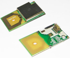
Laipac offers several low cost RF modules for high speed data transmission. Low cost modules include the TLP/RLP series of transmitters and receivers . These modules are very versatile, therefore perfect for OEM customers. We also offer a variety of Transceivers for voice, data & voice and data & voice & video. The transceivers are great for more complex, full duplex telemetry or communications.
RF Transceiver Module
Model
Main Features
Frequency
Voltage
Data Rate
Sensitivity
Max. Consumption
RF900DV
16 Channels
902.525~
904.625MHZ. & 902.525 ~
5V (Base) &
3.6V (Remote),
200Kbps~28.8Kbps
-103dB
80mA
TRF-2.4G High Speed Data/Transceiver 2.4Ghz Frequency : 2.4~2.524 GHz 3V Estimated 100mts @250Kbps ; 50mts @1Mbps, Line of Sight -90dB @250kbps
-80dB @1000kbps 18 mA@250kbps
WIRELESS USB DONGLE - AWP24U
WIRELESS USB DONGLE - AWP24U - RF and RFID
Digi-Key Part Number 748-1002-ND
Price Break Unit Price Extended Price
1 31.99000 31.99
10 24.99000 249.90
100 19.99000 1999.00
500 17.75004 8875.02
1000 16.99001 16990.01
Manufacturer Part Number AWP24U
Description WIRELESS USB DONGLE
Quantity Available 12
All prices are in US dollars.
Wireless USB - RF Transceivers™
To further extend the flexibility and programmablity of Cypress's Wireles portfolio, PRoC(TM) - Programmable Radio-system on-a Chip - integrates a flexible 8-bit microcontroller with the 2.4GHz radio transceiver in a single chip solution. The PRoC solutions offers a unique capability of component integration to enable extremely small form factor designs for low-power wireless systems.
Furthermore, Cypress's easy-to-use Wireless hardware and software tools reduce wireless complexity for customers, significantly reducing design cycles, from end-to-end wireless keyboard and mouse reference designs to production ready, pre-certified RF modules. Modules provide complete drop-in solutions, including the complete (silicon and all external components) printed circuit board (PCB) to meet maximum performance requirements. Cypress has partnerships with Ontario-based Artaflex, Fremont, CA-based Unigen, and Italy-based Aurel to offer a wide portfolio of wireless modules. Information and datasheets for these modules can be found on their websites:
|
transmitters modules at 433.92MHz
Model: TLP - F02
Remote Control (Transmitter)
FCC Certified
Frequency Range: 433.92MHz
Size: 50 x 38 x 11 (mm)
Battery: 12V
Button: 2 keys
transmitters modules at 433.92MHz
Model: TLP - F02
Remote Control (Transmitter)
FCC Certified
Frequency Range: 433.92MHz
Size: 50 x 38 x 11 (mm)
Battery: 12V
Button: 2 keys
2.4 Ghz. Transceiver - RF Transceiver-OEM
Specification
2.4Ghz. Data Transceiver" - TRF-2.4G TLP2.4G - High Speed Data/Transceiver 2.4Ghz
Specification :
* Frequency : 2.4~2.524 GHz
* Modulation type: GFSK
* Op. Voltage: 3V
* Output Power: +4dBm
* Data Rate: 1Mbps
* Small footprint size: 20.0 x 36.7 x 2.4mm
* Operating Tempeature: -40 ~ + 85 C
* Long range : estimated 100mts @250Kbps ; 50mts @1Mbps , Line of Sight
* Built-in antenna.
* Real full-duplex, including decoder, encoder and data buffer.
* Very low cost
* Applications: Telemetry, Wireless Toys, Remote Control, Wireless Speaker, Wireless Earphone or Walkie-Talkie, Wireless Mouse and Keyboard, Utility Meters Data Downloading ...etc
Model Description SPEC (PDF)
TRF-2.4G High frequency Transceiver module (GFSK) 2.4GHz
Symb Parameter(condition) Notes Min. Typ. Max. Units
VDD Supply voltage 1.9 3.0 3.6 V
TEMP Operating temperature -40 +27 +85 Centigrate
f op Operting frequency 1) 2400 2524 MHz
R GFSK Data rate direct mode 3) 250 1000 kbps
F CHANNEL Channel spacing 1 MHz
I VDD Supply current one channel 250kbps 18 mA
I VDD Supply current one channel 1000kbps 19 mA
I VDD Supply current two channels 250kbps 23 mA
I VDD Supply current two channels 1000kbps 25 mA
RX SENS Sensitivity at 0.1%BER(@250kbps) -90 dB
RX SENS Sensitivity at 0.1%BER(@1000kbps) -80 dB
Conditions: VDD=+3V,VSS=0V,T A =-40 centigrade to +85 centigrade
New 2.4 GHz RF Transceiver Nodules
Friday, August 20, 2010
A Simple Electronic Buzzer electronic
Category
- 2.4 Ghz. Transceiver (2)
- 230v circuits (2)
- 55 timer circuit. (2)
- 555 timer (3)
- actif high (1)
- activ low (1)
- Alarm (2)
- Alarm Circuit (1)
- Am Transmitter (1)
- Amplifer (2)
- Amplifier (7)
- AND gate (2)
- antenna (4)
- Antenna schema Circuit (2)
- atx (1)
- Audio (2)
- Audio Circuit (1)
- Battery Charger (2)
- biquad (1)
- buck (2)
- cable checker (1)
- CAN (2)
- Cars (4)
- charger (2)
- circuit ic (1)
- circuit long wire (2)
- Circuits (17)
- control (4)
- Control Kit tool (2)
- Controller (2)
- current limit (1)
- DC-AC (1)
- Detector Circuit (1)
- Digital circuit (6)
- Dimmer (1)
- dioda (1)
- Diode (2)
- DivX (1)
- Domestic (1)
- Drive (1)
- driver motor (1)
- Electrical Schematic Diagrams (1)
- electronic circuit (8)
- Emergency Light (2)
- Ethernet (2)
- Fast-Recovery Diodes (1)
- flasher (2)
- Flyback (1)
- flyback transformer (1)
- FM (2)
- Fun Circuits (3)
- h bridge (1)
- high voltage (1)
- hp tx1000 (1)
- indikator (1)
- insect repellant (2)
- intercom (1)
- interface (5)
- Inverter (2)
- IR (1)
- irda (1)
- l293d (1)
- Lecture Vedio (3)
- Levitation (1)
- Lights and L.E.Ds (3)
- logic gate (1)
- Magnetic (2)
- Magnetic Rotary Encoder (1)
- Microcontroller (10)
- motor control (1)
- Music (1)
- NE555 (1)
- notebook (1)
- optical mouse (1)
- or (1)
- oscillator (2)
- Oscillator Generator (1)
- Other Circuits (4)
- pic microchip (1)
- PIC16F (1)
- Power Amplifier (1)
- power supplies (2)
- power supply (4)
- Printer (2)
- Projects (1)
- psu (1)
- Push-Pull (2)
- pushbutton (1)
- radio (2)
- Rangkaian delay speaker (2)
- RCD Snubber (2)
- Reading Recommendations (6)
- Regulator (1)
- Relay and delay (2)
- repair (1)
- RF (1)
- rf transmitter (1)
- security (1)
- Sensor (3)
- Sensors (2)
- Simple Component (6)
- Snubber (4)
- Sound (1)
- spdif (1)
- switch (1)
- Switch-Mode (2)
- switching (2)
- telephone (2)
- timer (1)
- Tips and Tricks (17)
- toslink (1)
- touch sensor (1)
- touch switch (1)
- Transceiver Nodules (2)
- Transistor (1)
- transistor amplifier circuit (1)
- transmitter (5)
- ttl (1)
- Ultrasonic circuit (1)
- USB (3)
- Vedio (4)
- WIDER (1)
- Wireless (5)
- wlan antenna (1)
- zener (2)
About Me
- schema electronic
- New circuits and/or links are added regularly as a resource for beginners, hobbyists, engineers, inventors and consultants. Let us know what is missing or if you have a circuit to include in this collection.