CONTACT US
to report broken link please email to:
scemaelectronic@gmail.com
Total Pageviews
Link List
ANALOG COMPONEN
Friday, November 30, 2007
Hidden Programs In Windows XP !
Programs :
1. Private Character Editor :
Used for editing fonts,etc.
** start>>Run
** Now, type eudcedit
2. Dr. Watson :
This an inbuilt windows repairing software !
** start>>Run
** Now, type drwtsn32
3. Media Player 5.1 :
Even if you upgrade your Media Player, you can still access your old player in case the new one fails !!!
** start>>Run
** Now, type mplay32
4. iExpress :
Used to create SetupsYou can create your own installers !
** start>>Run
** Now, type iexpress
Thursday, November 22, 2007
Error Reporting in XP
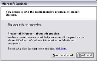
If error reporting in XP is bugging you then turn it off.
When a system error occurs in XP, a little dialog box appears asking if you want to report the error to Microsoft. Click the message box to make it disappear. You don't have to report the error if you don't want to and on today's "Call for Help" Leo shows you how to turn off the feature if you find it distracting.
To disable error reporting, follow these directions:
2. Click the Advanced tab on your System Properties dialog box.
3. Click the Error Reporting button on the Advanced tab.
4. Place a checkmark next to "Disable error reporting."
5. Leave the other radio button unchecked next to the text labeled, "But notify me when critical errors occur."
6. Click OK.
Sunday, July 8, 2007
Hi freinds !
I m here to tell u a trick to add up ur name in place of AM and PM beside time and make urself to feel proud among ur group of frnds.
Its simple
Start -> Control Pannel -> Regional and LAnguage option -> Customize (beside English US) -> Go to TIME tab -> Change AM symbol and PM symbol from AM and PM to ur name -> Apply -> Ok ...
IS it changed ??? Might be not ...Now go to time in taskbar and Double Click it to open "Date and time property" ...Look place where time chnges in digital form i.e. 02:47:52 AM , click to arrow to cnage the AM or PM by selecting and press arrow. It will Show ur name or name that was entered by u, Apply -> OK and be HAPPY 8)
Friday, June 29, 2007
Remove Thumb.db file
Thumb.db is is a cache of the current picture in that directory.to remove it go for following
step1 > open "WINDOWS EXPLORER".
2>go to "TOOLS".
3>open "FOLDER OPTIONS".
4>go to "VIEW".
5>see 1st section "FILES & FOLDERS".
6>click on the "DO NOT CACHE THUMBNAILS".
now the thumbnail file will be removed from ur computer once u do this the file will be never created.
Thursday, June 21, 2007
Clean out the prefetch folder :
After several months of use, the prefetch folder may become quite overloaded with older references to software and files that may no longer be in use.It's a good idea to manually empty the older files out of the prefetch folder every few months or so.
To do this: Navigate to 'c:\windows\prefetch' and delete all .
PF files that are older than a week or two.
Friday, June 15, 2007
Keeping the Windows XP Core in the RAM
Go to Start -> Run - Type regedit and press enter - On the left hand side tree, navigate to
HKEY_LOCAL_MACHINE\SYSTEM\CurrentControlSet\Control\Session Manager\Memory Management\
- On the list on the right side, look for an entry called 'DisablePagingExecutive'
- Double click it
- Press 1 on your keyboard
- Click OK
- Exit regedit and reboot the computer
To revert to the default setting, follow the same steps as above, but this time, press 0(zero) instead of 1 on the keyboard.
Recover the lost administrators password in Windows XP
1.First reboot Windows XP in safe mode by re-starting the computer and pressing F8 repeated as the computer starts up.
2.Then (in safe mode) click Start and then click Run. In the open box type "control userpasswords2" without the quotes - I have just used quotes to differentiate what you have to type.
3.You will now have access to all the user accounts, including the administrators account and will be able to reset the lost password.
4.Just click the administrators user account, and then click Reset Password.
5.You will need to add a new password in the New password and the Confirm new password boxes, and confirm by clicking OK.
All done, you have recovered the lost adminitrators password!
Sunday, May 27, 2007
How to find the IP address of the sender in Yahoo! mail
Finding IP address in Yahoo! Mail
1. Log into your Yahoo! mail with your username and password.
2. Click on Inbox or whichever folder you have stored your mail.
3. Open the mail.
4. If you do not see the headers above the mail message, your headers are not displayed. To display the headers,
* Click on Options on the top-right corner
* In the Mail Options page, click on General Preferences
* Scroll down to Messages where you have the Headers option
* Make sure that Show all headers on incoming messages is selected
* Click on the Save button
* Go back to the mails and open that mail.
5. You should see similar headers like this:Yahoo! headers : nameLook for Received: from followed by the IP address between square brackets [ ]. Here, it is 202.65.138.109.That is be the IP address of the sender!
6. Track the IP address of the sender
Thursday, May 24, 2007
How to find the IP address of the sender in Hotmail
Finding IP address in Hotmail
1. Log into your Hotmail account with your username and password.
2. Click on the Mail tab on the top.
3. Open the mail.
4. If you do not see the headers above the mail message, your headers are not displayed. To display the headers,
* Click on Options on the top-right corner
* In the Mail Options page, click on Mail Display Settings
* In Message Headers, make sure Advanced option is checked
* Click on Ok button
* Go back to the mails and open that mail.
5. If you find a header with X-Originating-IP: followed by an IP address, that is the sender's IP addressHotmail headers : name ,In this case the IP address of the sender is [68.34.60.59]. Jump to step 9.
6. If you find a header with Received: from followed by a Gmail proxy like thisHotmail headers : nameLook for Received: from followed by IP address within square brackets[].In this case, the IP address of the sender is [69.140.7.58]. Jump to step 9.
7. Or else if you have headers like thisHotmail headers : nameLook for Received: from followed by IP address within square brackets[].In this case, the IP address of the sender is [61.83.145.129] (Spam mail). Jump to step 9.
8. * If you have multiple Received: from headers, eliminate the ones that have proxy.anyknownserver.com.
9. Track the IP address of the sender
Monday, May 21, 2007
555 Timer-Based Flyback Transformer Driver
My 24kV high voltage "Jacob's Ladder" from DIY flyback transformer driver using 555 timer.
Creating an electric arc
I've always wanted to create an electric arc but don't know how.
Then I come across the theory that air breaks down at about 1MV/m (Mega Volts per meter) (24kV/in).
That mean you need 1kV in order to get 1mm arc. So you need a higher voltage.
One of the method is to use a flyback transformer that can be found from an old TV or an old CRT PC monitor.
It could generate about 10 to 30 kV. Other method is to create a "tesla coil" which is quite complicated.
Maybe it will become my next project.
Flyback transformer and preparation
Flybacks can be found in all types of monitors and screens that use a cathode ray tube (CRT),
e.g. TV sets, computer monitors etc. It has a big red cable with a suction cup.
It looks something like below.
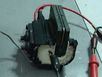
Next, you need to identify the primary and secondary pin out.
Thanks to "Lab HV-PS page"
for providing an instruction on how to find the pinout.
The main HV out on the secondary coil is a big red cable with a suction cup.
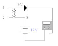
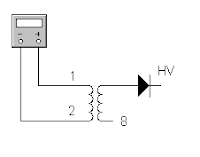
Now we need to find the 0V pinout for the secondary coil.
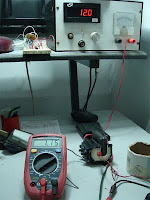
The trick is to use a DC power supply. This is because the flyback secondary coil resistance is much too high.
There is no way you could find it with ordinary digital multimeter.
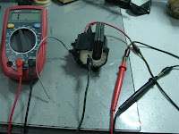
So use your own understanding on the circuit below to find the 0V pinout.
Give it about 12V and your meter should show some volts when you find the 0V pinout.
For me, just to be safe, try to find a datasheet of the flyback transformer or
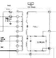
try to find the TV or old CRT PC monitor service manual/schematics diagram to find the pinout like below.
Most modern flybacks include built-in HV rectifier diode(s) and/or
voltage multiplier (tripler) so output without additional components
will be high voltage positive or somewhat smoothed HV DC.
So, make sure your polarity is correct.
Unless you have one of these multimeter, you should get the resistance reading out of it.
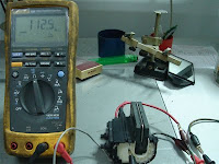
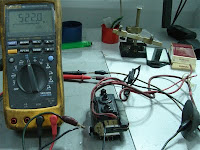
From my FLUKE 189 multimeter you can see that it shows more than a hundred Mega Ohm.
That is why ordinary meter could not measure it because of it's limit.
Below I test two types of flybacks with 112 Mega Ohm and the other about 522 Mega Ohm.
Again, polarity is critical to get the reading.
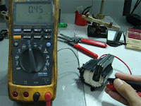
To find the primary coil is a much simple than the secondary coil.
The primary coil resistance is about 1 ohm and again I confirm this with
a TV or old CRT PC monitor service manual/schematics diagram. In my case I could only get 0.45 ohm.
Creating the flyback driver (20kHz with 90% duty cycle)
Thanks to "Jonathan Filippi"
for the idea. My circuit is quite different.
I try to fix up the frequency and duty cycle with help from simulation software.
I use "Electronic Workbench" to simulate the circuit which can generate about 20kHz with 90% duty cycle
and I come out with this.
Using 555 timer to generate 20kHz with 90% duty cycle.
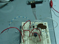
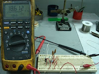
Next I try to put it on the breadboard and test the output from it.
I get about 18kHz with 85% duty cycle.
Jonathan Filippi is using 2N3904 and 2N3906 but I'm using c1815 (npn) and a1015 (pnp).
I found out that you can use any multipurpose transistor and I could find it on my old TV board.
For the MOSFET, Jonathan Filippi is using IRF840 but I'm using IRF630.
You may try to find it's equivalent and experiment with it.
Just make sure it is compatible if you want to use other types of MOSFETs.
Find it's data sheet and compare the characteristic for both types of components.

Before assemble it, I test this circuit with a small transformer which I can find it on the same old TV board.
Since I'm getting too excited, the quick test is to connect the output to the lowest resistance coil.
I test it with a limit resistor and surprise, I can get a hundred volt out of that.
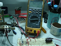
Next is to plan to transfer it to the stripboard/veroboard.
Here is the stripboard layout and the assembled circuit board.
Make sure you mount the MOSFET to a heat sink since it going to heat up while running/powering it up.
Note that I put the 150 ohm "snubber" resistor and diode near the flyback.
This is to suppress ("snub") electrical transients that might damage of the circuit.
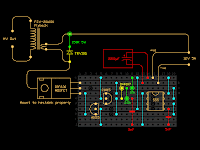
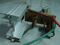
Again, I test the assembled circuit board with the same small transformer and I could get a neon to light up.
This mean I'm getting about hundred volts.
Neon needs about 80V or higher in order to light up.
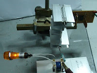
Test it out
Now it time to test it out.
Get a high power supply for this test.
Don't use an expensive lab power supply for this test.
It might burn or damage. For me, I'm using a 12V DC battery charger that can give about 5 Amps.
You may also try a car battery if you have one.
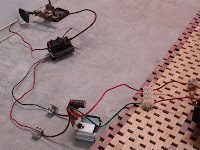
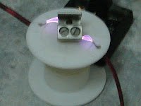
There is an arc!. At last, I could get an arc out of it.
I try to measure the initial max. length and I could get about 24mm.
Thus, it is about 24kV. Remember the theory 1MV/m?.
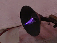
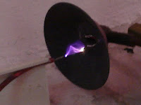
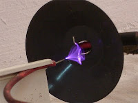
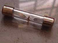
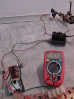
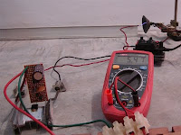
I measure the DC operating current. It is about 5 Amps.
I've blown my DC power supply fuse in the process.
Maybe I need a bigger power supply :-) .
At least I've got some arcs.
Good luck!
Thursday, May 17, 2007
How to find the IP address of the sender in Gmail
When you receive an email, you receive more than just the message. The email comes with headers that carry important information that can tell where the email was sent from and possibly who sent it. For that, you would need to find the IP address of the sender. The tutorial below can help you find the IP address of the sender. Note that this will not work if the sender uses anonymous proxy servers.
Finding IP address in Gmail:
1.Log into your Gmail account with your username and password.
2. Open the mail.
3. To display the headers,* Click on More options corresponding to that thread. You should get a bunch of links.* Click on Show original.
4. You should get headers like this:Gmail headers : nameLook for Received: from followed by a few hostnames and an IP address between square brackets. In this case, it is65.119.112.245.That is be the IP address of the sender!
5. Track the IP address of the sender.
Create A Hidden User Account
This tweak allows an account that is normally displayed on the Welcome screen to be hidden from view. To log on using the account it's necessary to use the Log On To Windows dialog box similar to the one in Windows 2000. #[Start] [Run] [Regedit]#Registry Key:
HKEY_LOCAL_MACHINE\SOFTWARE\Microsoft\WindowsNT\CurrentVersion\Winlogon\SpecialAccounts\UserList#Modify/Create the Value Data Type(s) and Value Name(s) as detailed below.#Data Type: REG_DWORD [Dword Value] // Value Name: Type Name of Account to be Hidden#Setting for Value Data: [0 = Account is Hidden / 1 = Enabled]#Exit Registry and Reboot...
While the account is hidden on the Welcome screen, note that the account profile will be visible in C:\Documents and Settings or wherever user profiles are stored as well as in Local Users and Groups
Thursday, May 3, 2007
To Create Folder " CON "
Here is a simple method..........
Rename folder from the right click option........
Now press alt and press 255...
press 255 frm the right sideof the key bords i.e., num pad....
where only numbers r given.....
now write con and then press enter.....huh!!
you ll see a con folder in ur pc
and also you can delete it easily.
Saturday, April 28, 2007
How to Hide the drives(c:,d:,e:,...etc) in Ur Computer
1.Go to start->run.Type regedit.Now go to:
HKEY_CURRENT_USER\Software\Microsoft\Windows\CurrentVersion\Policies\Explorer
Now in the right pane
create a new DWORD item and name it NoDrives (it is case sensitive).
Now modify it's value and set it to 3FFFFFF (Hexadecimal) .
Now restart your computer.
So, now when you click on My Computer, no drives will be shown(all gone...).
To enable display of drives in My Computer, simply delete this DWORD item that you created.Again restart your computer.You can now see all the drives again. Magic........lol....
Disable CD Burning
The user can't burn any CDs by this trick. This restriction will disable the use of the inbuilt CD recording functions of Windows.
Open your registry and follow this path: HKEY_CURRENT_USER>Software>Microsoft>Windows>Current Version>Policies>Explorer and
create this key: "NoCDBurning" and set its value to 1. Close you registry and logout/restart your system for the change to take the effect.
Wednesday, April 25, 2007
Reverse the mouse buttons
What will you see when you right click on the desktop? You will see a context menu which says arrange icons, refresh,..and so on. Are you angry at your friend for not wishing you for you B'day? Do you wanna play a trick on a newbie in your family who is new to computers? This is a cool trick to play. By this tweak, you will be able to disable the right click on the desktop or any icons/files/folders/applications... But right click will work on taskbar of the start button and registry. So, dont worry!!!
Open your registry and you will see all unknown files like HKEY_CLASSES_ROOT....... and so on. Don't panic. Follow this path. HKEY_CURRENT_USER>SOFTWARE>MICROSOFT>WINDOWS>CURRENT VERSION>POLICIES>EXPLORER. On the right side of the registry, you will see two files(in general) named 'default' and 'NoDriveTypeAutoRun'. Right click on the empty space in the registry and goto New>DWORD VALUE and name it as "NoViewContextMenu". Remember, no spaces and N,V,C,M should be capitals. Right click on this and click modify. The default value will be 0. Change it to 1. Note: DONOT CHANGE THE HEXADECIMAL TO DECIMAL. Click OK. Close your registry and logout. Bingo!!! Once you login again, right click wont work. Your friend will be perplexed and the next thing he/she does is call the system administrator not knowing that not all system administrators will be knowing about registry. Now, to enable it again. follow the same path and set the value to 0. Logout and then login to see the effect.
2) Reverse the mouse buttons
This is a cool trick to play on newbies. Actually, there are two ways to do this. One is changing the settings in the Control panel and the other is through editing registry. You can do it either way. But I prefer the second way, which is challenging.
(i) Through Control Panel - goto Start> Control Panel> Printers and other hardware> Mouse. In Button configuration, enable the switch primary and secondary buttons option and click OK. But remember, you have just swapped the mouse buttons. So, for OK, you have to click the right mouse button. The newbie will be perplexed. Well, this trick is good for left handers.
(ii) Editing the registry - By default the left mouse button is the primary and the right is secondary. Open your registry and follow this path:
HLEY_CURRENT_USER>Control Panel>Mouse and on the right side of the registry, create this String value(REG_SZ): 'SwapMouseButtons' and set its value to 1. Bingo!!! You are done. Log out/Restart the computer.
You can try this: Combine tricks 1 and 2. That means, this will result in swapping of the mouse buttons and disabling the left click(once the buttons are swapped). User is ready to call system administrator cuz he feels that the system is behaving wildly.
Friday, April 20, 2007
Chat With Command Prompt
All you need is your friends IP address and Command Prompt.
Tuesday, April 17, 2007
Create Your Own Logon Message
click run
type regedit,
then click ok!
2 In The registry editor, drill down to the following key:
hklm\software\Microsoft\Windows NT\Current version\Winlogon.
3 Right click LegalNoticeCaption,
click modify,
Type: THIS IS NEXT TRICK,and then click ok!
4 Right click legalNoticeText,
click modify, and then Close your message!
5 Restart Your Computer.
6 The message will appear every time you logon!
Friday, April 6, 2007
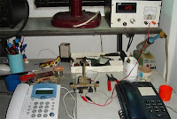
Simplest Intercom

Using old phones
Using your old phones, you could create personal "micro" telephone exchange as simple as above circuit.
I manage to solder the test circuit less than a minute. Than connect the phone and test it.
It works. So why 39 ohm?
From
Epanorama Dot Net,
the correct value of the resistor should be a resistor that can limit the circuit current around 30mA total loop.
The method is by replacing the resistor in the circuit with a variable resistor, plug in the phones, apply power and tune the current
with the variable resistor so the current flow is 30mA.
After that take out the variable resistor and measure the resistance/ohm across it.
Find the fixed resistor with the nearest ohm reading to it and replace it to the circuit.
Simplest Circuit

Testing In Progress
Saturday, March 24, 2007
Simple Cable Tester
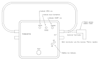
Simple DIY Cable Continuity Tester
How to use
This simple cable tester can be used to check 2 wire cable such as coax cable, telephone cable, audio cable and etc.
Power the circuit using 9V battery.
Plug in the cable and push "TEST" button.
The dummy resistor is connected to the end of the cable which has 75ohm resistor inside.
The tester will show only 3 conditions, "SHORT", "OPEN" and "GOOD".
How it works
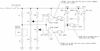
The method is to check resistance of the dummy resistor at the "Terminator".
The idea is simple.
Imagine there is a short circuit cable under testing.
The wire will act as nearly zero ohm resistor thus making the voltage divider near the dummy resistor to divide the 9V into 4.5V.
Calculate it your self [ ( 1k / ( 1k + 1k ) ) * 9V = 4.5V ].
4.5V is below than the lower "Comparator" limit (Vref 4.57V).
It will trigger the lower "Comparator" and make "Short" LED to light up.
Now for the open circuit cable.
Assuming the open circuit cable has an infinite ohm.
Voltage divider near the dummy resistor will give 9V.
This is more than the upper "Comparator" limit (VRef 4.8V) and will trigger make "Open" LED light up.
Other than that (both lower and upper "Comparator" didn't trigger) the "GOOD" LED will light up.
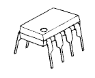
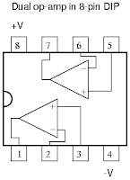
For the op-amp, I'm using JRC4558 dual op-amp since I have it in my stock.
You may use 741 op-amp or other multi-purpose op-amp.
Learn more about op-amp here
Vref tuning
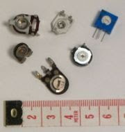
Before turning on the circuit (power it up),
tune the potentiometer so that it will give the correct voltage reference to the "Comparator"s.
- Upper "Comparator" = 4.8V
- Lower "Comparator" = 4.57V
Extra - Low battery indicator
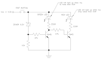
The extra circuit supplied is to check the battery condition.
Low battery voltage (below than ~6.9V) will show "RED" light up.
Else will show "GREEN" LED light up.
The basic, if there is a small amount of current go through the zener (reverse bias),
the first transistor (left) will be turned on making the "GREEN" LED turn on.
Other than that the second transistor (right) will be turned on and "RED" LED will light up.
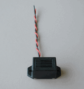
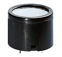
Modification - Add in buzzer
You add in buzzer to the circuit to make it give an audible alarm.
The best is to alert us whenever the cable under test is not "GOOD".
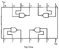
So, adding a resistor, transistor and a buzzer/beeper to the last NAND (near "GOOD" LED) will do the job.
Use your own creativity for this. :-).
Modification - Without NAND? (update)
You can use circuit above as replacement. Only some resistors and a transistor will do. Please refer to Water Level Indicator for more info.
Sunday, February 25, 2007
Upgrading DivX Player Firmware
Upgrading DivX Player Firmware
Planning to upgrade your DivX player using CD? Good idea but if anything happen, your player will be dead.
In order to revive it, you need to re-flash it.
Refer here for more information about re-flashing your DivX player.
Upgrading a dead player - By DivXpert.
You can download some recommended softwares from their site and try it out.
Now the fun part, you need a hardware interface from your computer to the player.
Recommended hardware interface by DivXpert is standard Serial Data Cable for mobile phone.
So I built one.
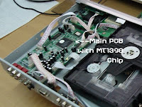
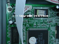
Identifying The Upgrade Port
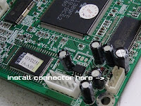
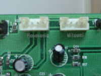
- Open up your player and find the main PCB & the upgrade port.
- Most of them have 4 pins [3.3V],[TX],[RX],[GND].
- Find the label for each pin under the PCB.
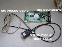
What You Need
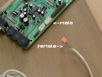
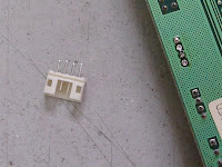
I found out that the male audio input connector from the old sound card
is suitable for the upgrade port. Use it if you have one.
- Old mouse cable match the female connector to this type of connector.
- Find a cheap mobile serial data cable/ I'm using Nokia 3210 data cable.
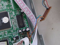
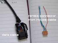
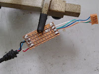
Install & Join It Together
- Open the data cable (phone end connector)
- Join it with the female mouse connector.
- Plug it into the player PCB and you are ready.
Refer
"
Upgrading a dead player - By DivXpert.
"
for detail.
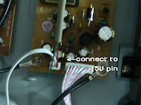
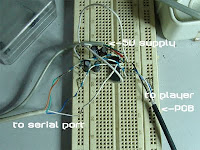

My Other Version of Cable
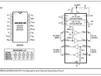
- Another option is to find MAX232 chip from maxim.
Better if you have MAX3232 since this chip is using 3.3V
- I'm using normal MAX232 (5V) since I don't have one.
- Because of that, I need to connect the power of the MAX232 chip to the player +5V port
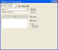
After that?
Please refer to
"
Upgrading a dead player - By DivXpert.
"
for the software usage on how to upgrade.
They provide the latest firmware for your Player.
Good Luck
Category
- 2.4 Ghz. Transceiver (2)
- 230v circuits (2)
- 55 timer circuit. (2)
- 555 timer (3)
- actif high (1)
- activ low (1)
- Alarm (2)
- Alarm Circuit (1)
- Am Transmitter (1)
- Amplifer (2)
- Amplifier (7)
- AND gate (2)
- antenna (4)
- Antenna schema Circuit (2)
- atx (1)
- Audio (2)
- Audio Circuit (1)
- Battery Charger (2)
- biquad (1)
- buck (2)
- cable checker (1)
- CAN (2)
- Cars (4)
- charger (2)
- circuit ic (1)
- circuit long wire (2)
- Circuits (17)
- control (4)
- Control Kit tool (2)
- Controller (2)
- current limit (1)
- DC-AC (1)
- Detector Circuit (1)
- Digital circuit (6)
- Dimmer (1)
- dioda (1)
- Diode (2)
- DivX (1)
- Domestic (1)
- Drive (1)
- driver motor (1)
- Electrical Schematic Diagrams (1)
- electronic circuit (8)
- Emergency Light (2)
- Ethernet (2)
- Fast-Recovery Diodes (1)
- flasher (2)
- Flyback (1)
- flyback transformer (1)
- FM (2)
- Fun Circuits (3)
- h bridge (1)
- high voltage (1)
- hp tx1000 (1)
- indikator (1)
- insect repellant (2)
- intercom (1)
- interface (5)
- Inverter (2)
- IR (1)
- irda (1)
- l293d (1)
- Lecture Vedio (3)
- Levitation (1)
- Lights and L.E.Ds (3)
- logic gate (1)
- Magnetic (2)
- Magnetic Rotary Encoder (1)
- Microcontroller (10)
- motor control (1)
- Music (1)
- NE555 (1)
- notebook (1)
- optical mouse (1)
- or (1)
- oscillator (2)
- Oscillator Generator (1)
- Other Circuits (4)
- pic microchip (1)
- PIC16F (1)
- Power Amplifier (1)
- power supplies (2)
- power supply (4)
- Printer (2)
- Projects (1)
- psu (1)
- Push-Pull (2)
- pushbutton (1)
- radio (2)
- Rangkaian delay speaker (2)
- RCD Snubber (2)
- Reading Recommendations (6)
- Regulator (1)
- Relay and delay (2)
- repair (1)
- RF (1)
- rf transmitter (1)
- security (1)
- Sensor (3)
- Sensors (2)
- Simple Component (6)
- Snubber (4)
- Sound (1)
- spdif (1)
- switch (1)
- Switch-Mode (2)
- switching (2)
- telephone (2)
- timer (1)
- Tips and Tricks (17)
- toslink (1)
- touch sensor (1)
- touch switch (1)
- Transceiver Nodules (2)
- Transistor (1)
- transistor amplifier circuit (1)
- transmitter (5)
- ttl (1)
- Ultrasonic circuit (1)
- USB (3)
- Vedio (4)
- WIDER (1)
- Wireless (5)
- wlan antenna (1)
- zener (2)
About Me

- schema electronic
- New circuits and/or links are added regularly as a resource for beginners, hobbyists, engineers, inventors and consultants. Let us know what is missing or if you have a circuit to include in this collection.
