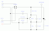
Descrition & Circuit
This project is taken from
www.electronics-lab.com.
With some modification, I create my own version of FM Telephone bug complete with stripboard layout.
Theortically, the frequency range is from 88MHz to 94MHz but you may experiment with the coil structure to tune it
Circuit

|
Strip Board Layout

|
Parts List
Diode |
IN4384 |
4 |
|
LED |
1 |
Resistor |
12k |
1 |
|
1k |
1 |
|
200R |
1 |
Capacitor |
470p |
1 |
|
330p |
1 |
|
25p |
1 |
|
12p |
1 |
Transistor |
A933(PNP) |
1 |
Coil |
*See note |
1 |
*Coil note
7 or 8 turns of 22AWG(diameter .6mm) around 9/64inch(3.6mm)
drill bit. Antenna using the same wire 22AWG, 5inch long
Picture
Compact!

With antenna!

Put it online!

Get ready to tune your radio!

Description and CircuitMake your own lab power supply complete with adjustable voltage and constant current source. Using single IC (LM324)
Here is the circuit.

Strip Board Layout.

Part List1 LM324 Opamp 1 Ammeter 100 µA 1k ohm 1 Voltmeter 6 IN4001 1 Zener Diode 9.1V 1 Full-Wave Bridge Rectifier 1 LED 2 NPN Transistor, 2N3055 1 NPN Transistor, BC109C 1 Transformer 2 E-Capacitor 2200µF 1 Potentiometer 5k ohm linear 1 Potentiometer 10k ohm linear 1 Resistor 500 ohm 2 Resistor 2.2k ohm 1 Resistor 560 ohm 1 Resistor 6.2k ohm 2 Resistor 68k ohm 1 Resistor 0.22 ohm 4 Resistor 4.7k ohm
Component Image.

LM324
|

2N3055
|
Some Pictures.  
| 


