 The value of R1, R2, C4, and C5 should be chosen in order to keep at least 12V in Vs.
Please connect C4 (>1μF) and C2 (<1μF).
ZCT and load resistance RL of ZCT are connected between input pin 1 and 2.
Protective resistance (RP=100Ω) must be insurted.
RL and amplifier’s output (in Pin 4) regulates sensitivity current
External capacitor C1 between pin 4 and GND is used for noise removal.
Please connect a varistor or a diode (2 pcs.) to ZCT in parallel, because of when large current is grounded in the
primary side (AC line) of ZCT, the following situation can be abandoned: The wave form in the secondary side of
ZCT is distorted and some signals do not appear in the output of amplifier.
Please connect capacitor (about 0.047μF) between pin 6 and pin 7.
Capacitor C6 between pin 1 and GND is about 0.047μF for removing noise.
M54123L
EARTH LEAKAGE CURRENT DETECTOR
DESCRIPTION
The UTC M54123L is a semiconductor integrated circuit with
amplifier for a high-speed earth leakage circuit breaker.
For the amplifying parts of earth leakage circuit breaker, the
UTC M54123L consists of differential amplifier, latch circuit and
voltage regulator.
In normal operating, the UTC M54123L should be connected
to the secondary side of the ZCT (zero current transformers). Here
the ZCT detects leakage current different amplifiers’ both input.
Then the signals which have been amplified are integrated by
an external capacitor. The integrated signal connects to the input
terminal of latch circuit whose output is suitable for the
characteristics of high- speed earth leakage circuit breaker.
Until the input voltage reaches the fixed level, latch circuit
doesn’t become high. Then drives a thyristor which is connected to
latch circuit’s output terminal.
FEATURES
* With good input sensitivity current temperature characteristics
* High input sensitivity :VT=6.1mV (Typ.)
* Only need low external component count
* High noise and surge-proof
* Low power dissipation :PD=5mW (Typ.)
* May be used both as 100V and 200V.
* Wide temperature range : from -20 °C to +80°C
Datasheet
http://www.unisonic.com.tw/datasheet/M54123L.pdf
 SYSTEM IMPLEMENTATION
 MCP2515
Description
Microchip Technology’s MCP2515 is a stand-alone
Controller Area Network (CAN) controller that implements
the CAN specification, version 2.0B. It is capable
of transmitting and receiving both standard and
extended data and remote frames. The MCP2515 has
two acceptance masks and six acceptance filters that
are used to filter out unwanted messages, thereby
reducing the host MCUs overhead. The MCP2515
interfaces with microcontrollers (MCUs) via an industry
standard Serial Peripheral Interface (SPI).
Features
• Implements CAN V2.0B at 1 Mb/s:
- 0 – 8 byte length in the data field
- Standard and extended data and remote
frames
• Receive buffers, masks and filters:
- Two receive buffers with prioritized message
storage
- Six 29-bit filters
- Two 29-bit masks
• Data byte filtering on the first two data bytes
(applies to standard data frames)
• Three transmit buffers with prioritizaton and abort
features
• High-speed SPI™ Interface (10 MHz):
- SPI modes 0,0 and 1,1
• One-shot mode ensures message transmission is
attempted only one time
• Clock out pin with programmable prescaler:
- Can be used as a clock source for other
device(s)
• Start-of-Frame (SOF) signal is available for
monitoring the SOF signal:
- Can be used for time-slot-based protocols
and/or bus diagnostics to detect early bus
degredation
• Interrupt output pin with selectable enables
• Buffer Full output pins configurable as:
- Interrupt output for each receive buffer
- General purpose output
• Request-to-Send (RTS) input pins individually
configurable as:
- Control pins to request transmission for each
transmit buffer
- General purpose inputs
• Low-power CMOS technology:
- Operates from 2.7V – 5.5V
- 5 mA active current (typical)
- 1 µA standby current (typical) (Sleep mode)
• Temperature ranges supported:
- Industrial (I): -40°C to +85°C
- Extended (E): -40°C to +125°C
http://ww1.microchip.com/downloads/en/DeviceDoc/21801d.pdf
 MCP2502X/5X
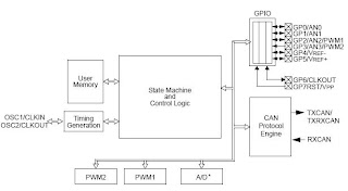
Description
The MCP2502X/5X devices operate as I/O expanders
for a Controller Area Network (CAN) system,
supporting CAN V2.0B active, with bus rates up to
1 Mb/s. The MCP2502X/5X allows a simple CAN node
to be implemented without the need for a
microcontroller.
The MCP2502X/5X devices feature a number of
peripherals, including digital I/Os, four-channel 10-bit
A/D (MCP2505X) and PWM outputs with automatic
message transmission on change-of-input state. This
includes an analog input exceeding a preset threshold.
Features
• Implements CAN V2.0B
- Programmable bit rate up to 1 Mb/s
- One programmable mask
- Two programmable filters
- Three auto-transmit buffers
- Two message reception buffers
- Does not require synchronization or
configuration messages
• Hardware Features
- Non-volatile memory for user configuration
- User configuration automatically loaded on
power-up
- Eight general-purpose I/O lines individually
selectable as inputs or outputs
- Individually selectable transmit-on-pinchange
for each input
- Four 10-bit, analog input channels with
programmable conversion clock and VREF
sources (MCP2505X devices only)
- Message scheduling capability
- Two 10-bit PWM outputs with independently
programmable frequencies
- Device configuration can be modified via
CAN bus messages
- In-Circuit Serial Programming™ (ICSP™) of
default configuration memory
- Optional 1-wire CAN bus operation
• Low-power CMOS technology
- Operates from 2.7V to 5.5V
- 10 mA active current, typical
- 30 µA standby current (CAN Sleep mode)
• 14-pin PDIP (300 mil) and SOIC (150 mil)
packages
• Available temperature ranges:
- Industrial (I): -40°C to +85°C
- Extended (E): -40°C to +125°C
http://ww1.microchip.com/downloads/en/DeviceDoc/21664D.pdf


